Element | Description | |||
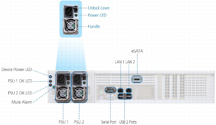
Device Power LED | A LED indicating whether the C800 is operational: | |||
State | Explanation | |||
On (Green) | The C800 is on. | |||
Off | The C800 is off. | |||
PSU 1 / PSU 2 | The C800's power supplies. | |||
PSU Power LEDs | A LED for each power supply, indicating whether it is operational: | |||
State | Explanation | |||
On (Green) | Input power detected. | |||
Off | No input power. | |||
PSU Unlock Levers | A lever for each power supply, enabling one to unlock it. | |||
PSU 1 OK LED / PSU OK 2 LED | A LED for each power supply, indicating whether it is in use: | |||
State | Explanation | |||
On (Yellow) | The power supply is in use. | |||
Off | The power supply is not in use. | |||
PSU Handles | A handle for each power supply, enabling one to remove it. | |||
Mute Alarm | If both power supplies are installed, and one of the power supplies fails or loses power, an alarm signal will sound. Press this button to mute the power supply alarm. | |||
Serial Port | A serial (RS-232) console port used for connecting to the C800 console. The console can be used for advanced troubleshooting and maintenance operations. | |||
USB 2.0 Ports | Four USB 2.0 ports used for connecting USB drives. Note that you can connect more than four USB drives, by connecting a powered USB hub. Be sure to use a powered hub, in order to avoid exceeding the power capacity of the USB ports. | |||
eSATA | An eSATA port used for connecting the C800 to a SATA drive. | |||
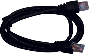
LAN 1 / LAN 2 | Two Ethernet ports used for connecting the C800 to your Ethernet LAN switch or router. Connect the Ethernet cables provided in the C800 package to these ports. To use both ports in parallel, configure link aggregation, as described in Enabling/Disabling Link Aggregation. For best performance, use a Gigabit-capable Ethernet switch. | |||
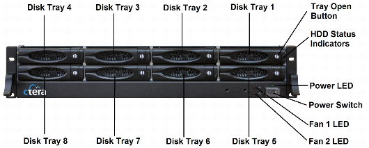
Element | Description | |||
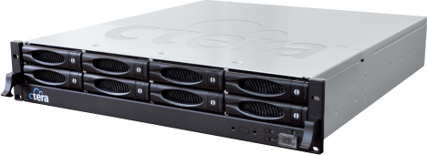
Disk Tray 1-8 | Eight disk trays for installing hard drives. | |||
Tray Open Button | Each disk tray has a Tray Open Button, which serves the following purposes: Indicates whether the disk tray is locked. When the button's groove is horizontal, the disk tray is locked. When it is vertical, the disk tray is open. Enables you to lock/unlock the disk tray, by using one of the disk tray keys to turn the button until its groove is horizontal/vertical. Enables you to open the disk tray. Upon pressing the button, the outer panel of the disk tray (visible in the preceding diagram) becomes a lever that can be used to pull the disk tray out of the cloud storage gateway. | |||
HDD Status Indicators | Each disk tray has two LEDs that indicate its status: | |||
LED | State | Explanation | ||
Upper LED | Blinking (Blue) | Disk activity | ||
Lower LED | On (Green) | OK | ||
On (Red) | Disk failure | |||
Blinking (Red) | RAID array failure | |||
Power LED | A LED indicating whether the system is operational: | |||
State | Explanation | |||
On (Green) | The system is operational. | |||
Off | The system is not operational. | |||
Power Switch | A switch used for turning the cloud storage gateway on and off and resetting it. The switch is covered by a clear plastic cover that must be lifted in order to access it. | |||
Fan 1 LED / Fan 2 LED | A LED for each fan, indicating whether the fan has failed: | |||
State | Explanation | |||
On (Red) | The fan has failed. | |||
Off | The fan is operational. | |||